Place Profile Intersection Point
 Used to indicate in a Profile
View where one element crosses another.
Used to indicate in a Profile
View where one element crosses another.
You can access this tool from the following:
Use the Place Profile Intersection Point command to indicate in a Profile View where one element crosses another. The point is placed at the station and elevation of the intersected element. The intersected element must have a designated active profile.
-
Select the Open Profile Model icon.
-
When you move the cursor into the Plan View, it is accompanied by a command prompt that says, "Locate Plan Element", so select the element with which you wish to work in profile.
-
The cursor is now equipped with a prompt that says, "Select or Open View".
-
Open the Civil Tools task pane to the Vertical Geometry section then click the Place Profile Intersection Point icon.
-
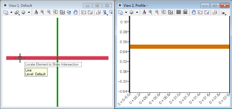
When you move the cursor into the Plan View, it is equipped with a prompt that says, "Locate Element to Show Intersection", so move the cursor to an intersecting element then data point.
-
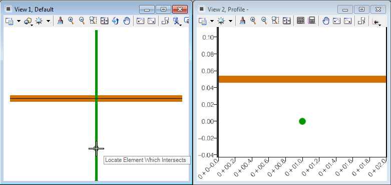
The cursor is now equipped with a prompt that says, "Locate Element which Intersects", so select the other intersecting element.


Properties
To View the new element's properties, equip the Element Selection tool.

Select the desired element in the Profile View then let the cursor hover over it. Click the Properties icon to access rule data for the chosen element.
Profile Intersection Point tool.
The Profile Intersection Point tool to allow the use of a selection set. We can demonstrate this a couple of different ways.
For example, there are 3 elements that cross main alignment: A storm sewer, An alignment, and A conduit.
Example 1- Select the main alignment and open its profile.
- Using a MicroStation Select Set.
- In the 2D view, select all 3 crossing elements to create a MicroStation selection set.
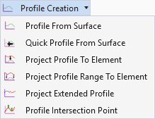
- Select Geometry > Profile Creation > Profile Intersection Point
- As prompted, ID the main alignment.
- Now issue a DP to accept the Selection Set.
Example 2 - All 3 intersection points will be placed in the profile.
- Using a Graphical Filter.
- With the 2d view active, select Geometry > Design Elements > Select by Graphical Filter
- Select an appropriate graphical filter and issue a DP to create the selection set.
- With the selection set created, now select Geometry > Profile Creation > Profile Intersection Point
- As prompted, ID the main alignment.
- Now issue a DP to accept the Selection Set.
- All 3 intersection points will again be placed in the profile.